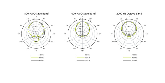
The directivity of a speaker is an important characteristic when defining the size of the listening zone, and it determines how the frequencies will balance, depending on the position of the listener.
The problem is that it’s impossible to have a constant directivity for all audible frequencies. Which results in it being pretty hard to get an identical level and frequency response for every listening position.
Definition and graphical representation
Directivity can be described as the frequency response relative to the listening position. Sound pressure level is measured at different points by placing a mic in a circle whose center is the speaker (in practice, the speaker is turned at different angles for each measurement during the test). This is done for the different frequency bands the speaker covers. This way you get polar plots where you can read the sound dispersion depending on the frequency, both on the vertical and horizontal axis. The central axis corresponds to 0°, perpendicular to the cabinet’s plane. The mic ought to be centered on the most directive element, namely the tweeter, and at an adequate distance so that the readings are significant.

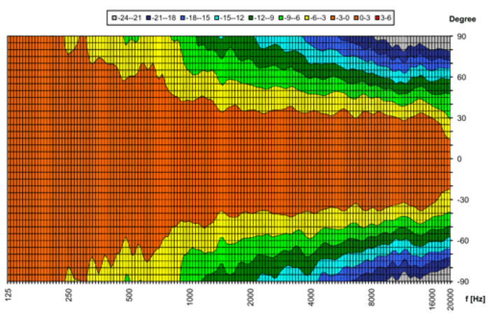
The isobar diagram in another type of representation. It shows the frequency on the horizontal axis and the angle in relation to the speaker on the vertical axis. The different zones delimited by the curves represent differences in acoustic pressure in relation to the central axis. Finally, for a quick overview, manufacturers often display the directivity in the form of two mean values: one for the horizontal coverage angle and one for the vertical coverage angle (for example, h x v: 90° x 40°). In practice, a constant directivity across the entire spectrum is very hard to accomplish.

Physical constraints
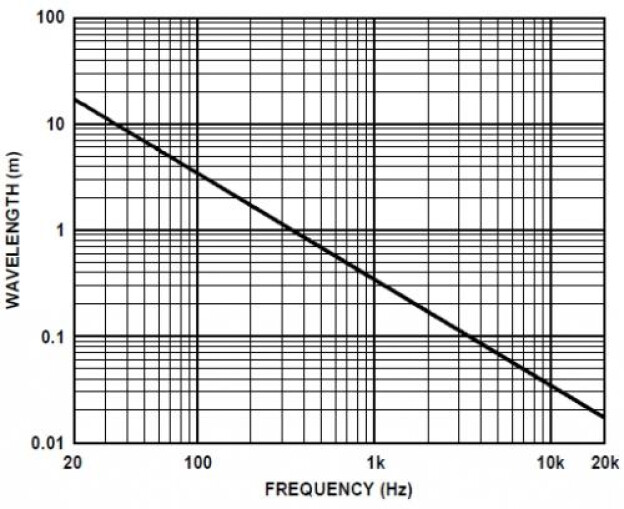
Since the wavelength of high frequencies is much shorter than that of low frequencies (ranging from cm to tens of meters), speakers don’t have an identical dispersion angle across the entire frequency spectrum. Depending on whether you are on or off axis, you can tell a difference in timbre. The farther away from the axis, the faster high frequencies are attenuated compared to lows. And the more obvious the directivity differences between highs and lows, the more unbalanced the reverberated sound of the room at the speaker position.
The source, i.e. the speaker and its driver, ought to be large enough in relation to the wavelength of the frequencies that it reproduces, in order to keep control over the directivity. To try to control the dispersion angle in the bottom end you’d need gigantic and untransportable speakers.
Relationship between frequency and wavelength
Many efforts have been made to solve these directivity issues, especially in terms of tweeter design (hemispherical diaphragms, acoustic lenses, horn drivers, etc), to try to counteract their natural hyperdirectivity. In the low end, the idea of coupling several units to simulate a much bigger loudspeaker has been in use for quite some time. There are even so-called “cardioid” installations where several subs are placed in very specific positions. The idea behind this concept is to try to eliminate the dispersion of the sound wave from the back and the sides with the use of additional subs for a more precise control of the position, polarity, phase, and level. This allows you to attenuate unwanted reflections in a room and avoid them from interfering with the mics on stage. The downside is that it requires more gear and time to install.


